Through our dozens of years of market feedback and technical experience, we have observed that failures in RF coaxial fixed attenuators predominantly occur in the ≥200 W( CW) power range. The vast majority of these failures manifest as burnt-out internal resistor elements. This article is to address causes of failure, failure symptoms, and preventive countermeasures, also we have elaborated why it is important to monitor the case temperature.
1.Causes of Failure in High-Power Attenuators ≥200W
1.1 Thermal Management Failure
The fundamental cause of failure in high-power attenuators (≥200W) is inadequate thermal management. For example, with a 200W input signal and 30 dB attenuation, approximately 199.8 W of power is dissipated as heat within the device. If this heat cannot be effectively dissipated—due to factors such as insufficient airflow, or poor contact between the mounting surface and the attenuator housing, heat will accumulate rapidly, leading to thermal destruction of the internal resistive elements.
1.2 Impedance Mismatch (High VSWR)
When the system connected to the attenuator exhibits a high Voltage Standing Wave Ratio (VSWR), a portion of the incident power is reflected back toward the attenuator. This increases the actual power dissipation beyond the nominal input level, significantly raising the risk of overload and thermal failure.
1.3 Signal Type
Pulsed Signals: High peak power (pulse width & duty cycle should be considered as well) can cause localized overheating and voltage breakdown before heat has time to conduct away from the resistive element, even if the average power is not in excess.
1.4 Excessive Average Power
Input power exceeding the rated average will cause permanent damage and failure. Operation must be limited to the nominal power.
1.5 Input/Output Connection Reversal
In high-power attenuators, the internal resistor network is designed with a power-gradient distribution. Reversing the input and output ports forces low-power-rated resistors to handle excessive power, resulting in immediate or accelerated failure.
2.Failure Manifestations
2.1 Electrical Performance Anomalies
Degraded VSWR: Initial VSWR may appear normal, but after several minutes of operation, it deteriorates sharply. 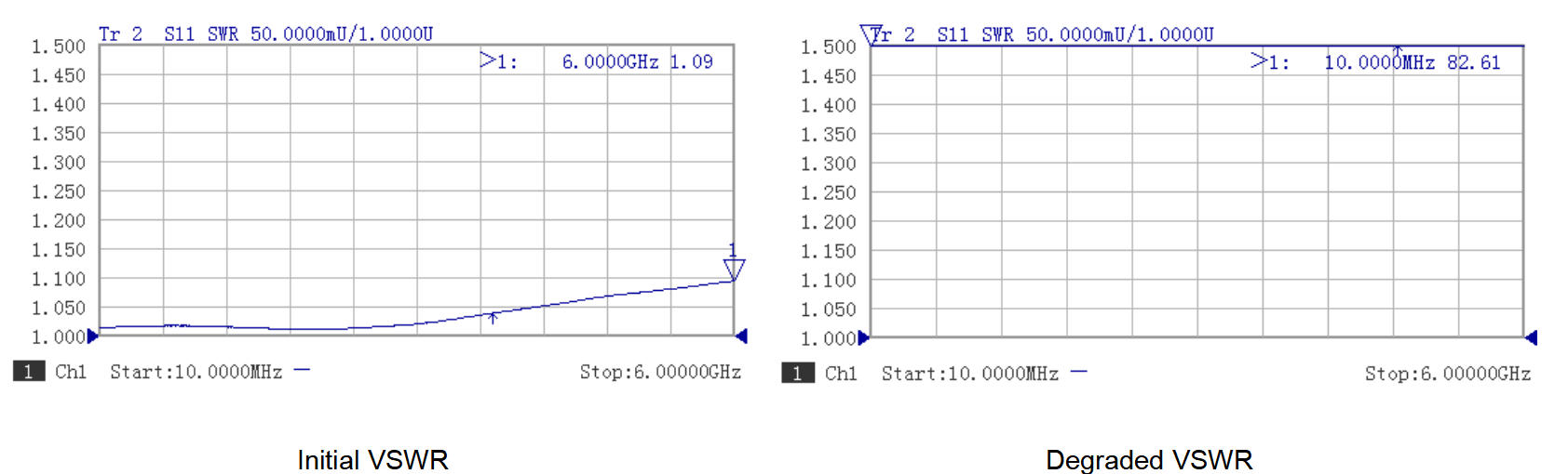
Attenuation shift: Attenuation value shifts abruptly from its normal data, causing unstable output power and system malfunction.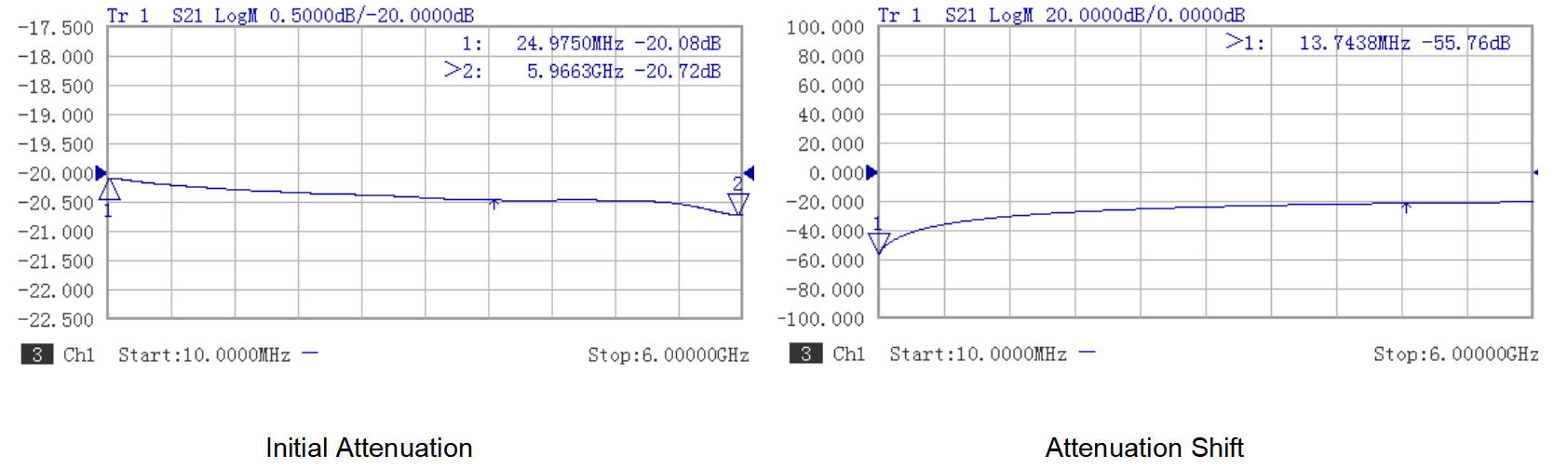
2.2 Physical Damage Indicators
Burnt Resistor Elements: Localized cracks or burnout of the resistive film.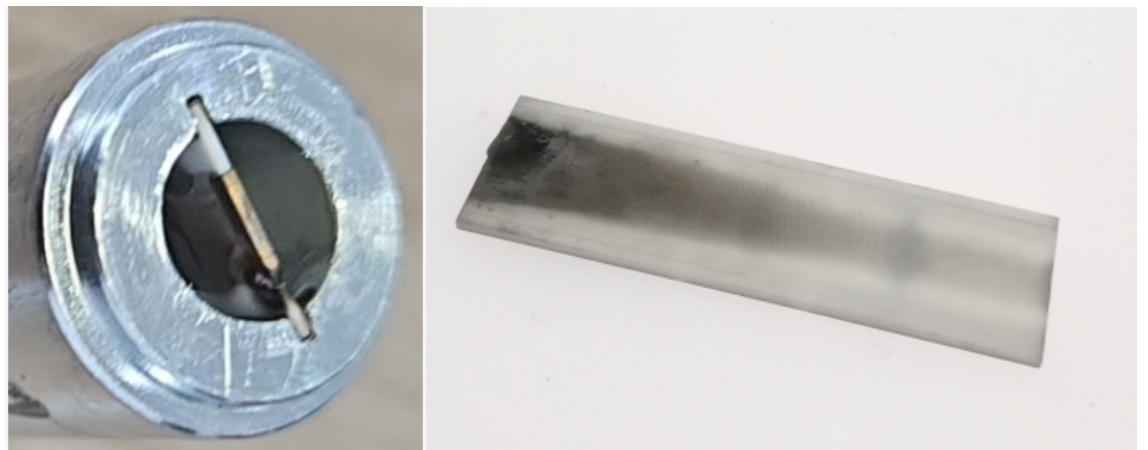
Connector Dielectric Damage: Carbonization of insulating materials due to excessive temperature.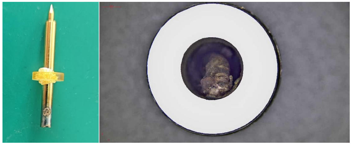
Housing Discoloration: Heat sink discoloration under extreme thermal stress.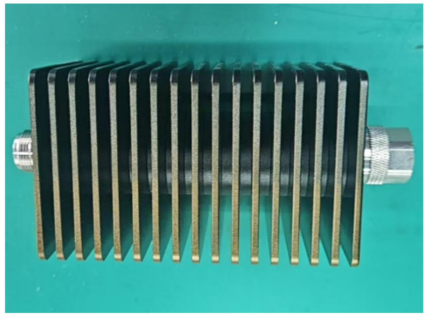
3.Preventive Measures to Avoid Attenuator Failure
4.1 Why Ambient Temperature Measurement Is Not Recommended
The term “ambient temperature” lacks a standardized definition. It may refer to:
– Air temperature near the component,
– Internal chassis air temperature,
– Laboratory bench temperature, or
– Inlet/outlet airflow temperature.
This variability introduces significant uncertainty into thermal design and power derating calculations.
In real-world systems, the local environment around the device is inevitably heated by the system’s own operation, making it impossible to measure a truly “undisturbed” ambient temperature. Consequently, power ratings based on ambient temperature are often unreliable.
Since permanent failure in coaxial attenuators is predominantly induced by excessive internal temperatures resulting from inadequate heat dissipation, continuous monitoring of the attenuator's case temperature is essential to ensure operational safety.
4.2 Advantages of Case Temperature Monitoring
4.2.1 Case temperature integrates the net effect of all thermal factors—including airflow, mounting contact quality and installation direction, and system congestion etc.,providing a real-time assessment of actual heat dissipation capability.
4.2.2 Users can quickly assess safety by touch or non-contact measurement. The measurement location is recommended in the center of the attenuator housing, and the recommended tools can be Infrared (IR) thermometer (set emissivity to 0.85–0.90 for black-anodized heat sink) or use thermocouple which has higher accuracy than thermometer.
Suggested Safety Thresholds for Case Temperature:
Normal range: < 70°C (suitable for continuous operation)
Warning range: 85°C-90°C (Action needed:cooling or reduce input power)
Critical range: > 100°C (immediately enhance cooling or reduce power)
5.Our Technical Countermeasures
5.1 Heat Sink Design
The heat sink geometry in our convection-cooled attenuators, including its overall size and fin spacing, is meticulously engineered to achieve optimal thermal resistance.
5.2 Advanced Material Selection
Our attenuators rated >5W utilize high-thermal-conductivity substrates (Beryllium Oxide, BeO). The resistive film and ceramic substrate are engineered with matched coefficients of thermal expansion (CTE), minimizing thermomechanical stress during thermal cycling.
5.3 Enhanced Quality Control
All units (>100W average) are subjected to pre-shipment power test till case temperature exceeds 85℃. This test identifies potential early-life failures due to manufacturing or material issues before shipment.
Conclusion
Based on our extensive field experience and continuous engineering refinement, we have established thermal management as the cornerstone of reliability in high-power RF coaxial fixed attenuators. By integrating thoughtful model selection, rigorous installation practices, and real-time thermal surveillance, users can greatly enhance the service life and operational reliability of their RF systems.
View this article in PDF format
